
WICS coil design
The circuit design and prototype of the WICS coil are shown in Figs. 2(a and b), respectively. The resonance frequency of WICS coil was adjusted to match the Larmor frequency of the 3 T MRI system (Achieva, Philips Healthcare, Amsterdam, Netherlands) at 127.8 MHz. In our study, the total bandwidth is 1.9 MHz (i.e., a plus or minus 0.95 MHz). According to our measurement, the quality factor of the WICS coil is 67.7 and its full width at half maximum is 1.90 MHz. Because of this, a coil frequency centered at 127.8 MHz within a range of 1.90 MHz is acceptable. The WICS coil consists of a copper circular wire (diameter of 4 cm), a 16-pF capacitor (Voltronics, USA), a variable capacitor (NMKM10HV, Voltronics, USA) and a detune circuit. We used a network analyzer to check the resonance frequency of WICS coil and fine-tune the coil frequency during the experiment setup to ensure that frequency variation stays within the acceptable error range. To ensure signal homogeneity and the “receive-only coil” nature of the WICS coil, two passively crossed diodes (UM9989, Microsemi) were used to decouple the resonance circuit. Theoretically, it is sufficient to use only a pair of crossed diodes, but we decided to use two pairs of crossed diodes to increase its withstand surge voltage. When high-power RF-pulses are applied, the WICS coil is simultaneously detuned to prevent coupling effects in the transmit mode of the MR system26. For WICS coil decoupling validation, we put a double loop probe near the WICS coil to check the S21 difference while the WICS coil at on-resonance or off-resonance states, by applying a DC voltage (5 V) to turn on/off the cross-diodes. The loops of probe have the same diameter of 6 mm and are overlapped for completely decoupling each other. Note that the amount of decoupling in our case was 20 dB according to decoupling validation method described above.
Figure 2
(a) Circuit diagram and (b) photograph of the WICS coil. The shallow shape of the WICS coil enables a close contact with the HIFU transducer during HIFU ablation. (c) Photograph of WICS coil implemented in the HIFU transducer. Increased SNR is beneficial to improve the temperature accuracy of MR thermometry. To enhance the SNR of the focal region, the home-made WICS coil was positioned to surround the HIFU transducer inside the MRI scanner. (d) Schematic and (e, f) photographs of the home-made reflecting transducer. (g) Illustration of the experimental setup. The HIFU transducer was placed on a rat thigh, and the glass in front of the piezoelectric ceramic reflects the HIFU power into the rat thigh.
The WICS coil was mounted on a 3D-printed hollow shell (Polylactic Acid). The diameter of the WICS coil is 4 cm. The proposed shell shape was designed to support the MRgHIFU setup so that the HIFU transducer is surrounded by the WICS coil, ensuring higher image quality in the heated region [Fig. 2c]21.
Theory of MR-based temperature measurement
The MR temperature measurements were analyzed based on the proton resonance frequency (PRF) shift method as follows27,28,29,30:
$$ Delta T = frac{emptyset left( t right) – emptyset left( 0 right)}{{gamma B_{0} alpha TE}} $$
(2)
where, (gamma ) is the gyromagnetic ratio,({B}_{0}) is the amplitude of the static field,(alpha (-0.01mathrm{ ppm}/ ^circ mathrm{C})) is the temperature-dependent coefficient for tissue, TE is the echo time of the sequence, (boldsymbol{varnothing }left({varvec{t}}right)) is the phase at time t, (boldsymbol{varnothing }(0)) is the phase before heating.
The SNR affects the accuracy of (Delta mathbf{T}) calculated from Eq. (2). Temperature accuracy (({sigma }_{T})) is inversely proportional to the SNR of the magnitude image31:
$$ sigma_{T} sim frac{1}{SNR times TE} $$
(3)
Thus, the SNR is a crucial factor affecting temperature accuracy. A higher SNR results in improved temperature accuracy. Note that temperature accuracy in this study indicates how close temperature values obtained from MR thermometry are to actual temperature values. Improved temperature accuracy indicates better temperature precision.
Reflecting HIFU transducer
A home-made reflecting HIFU transducer was designed for this study. The schematic drawing and prototype of the transducer are shown in Fig. 2(d,e,f). A 4-MHz piezoelectric ceramic was mounted inside a 3D-printed shell (Polylactic Acid) and a glass piece was placed 45° in front of the piezoelectric ceramic to reflect the HIFU power, changing the direction of the HIFU power. The HIFU power then passes through a thermoplastic urethane (TPU) membrane to reach the target tissue. A gear structure located behind the piezoelectric ceramic (at the tail-end of the transducer) can be turned manually to move horizontal bar attached to the piezoelectric ceramic, changing the distance between the piezoelectric ceramic and glass piece, which then changes the depth of the HIFU focal zone. Two water pipes were used to circulate water inside the transducer to dissipate extra heat produced.
MR thermal mapping validation study
To verify the accuracy of MR thermometry, measurement of the actual temperature change by using a fiber-optic thermometer was performed to compare with MR thermometry results. However, this validation method is impractical in HIFU ablation experiments because the HIFU transmission interferes with the fiber-optic thermometer. Thus, we used a hot water pipe to heat the pork tenderloin (instead of HIFU transmission) to validate MR thermometry results during heating. A water pipe filled with circulating hot water (70 °C was pierced through the pork tenderloin, and a fiber optic thermometer used to record the actual temperature was placed next to the water pipe.
Experimental setup is shown in Fig. 3. The experimental setup and anatomical localization scan took approximately 20 min. The T2-weighted images and temperature mapping described in this paper were acquired with turbo spin echo and gradient echo pulse sequences, respectively. The sequence parameters applied for T2-weighted images used for positioning were field-of-view (FOV) = 230 × 184 mm2, matrix size = 400 × 256, repetition time (TR)/TE = 3000/80 ms. Sagittal sections were used for positioning. After T2 images were acquired, MRI temperature measurements without and with heating via hot water circulation were performed with parameters: TR of 16 ms, TE of 12 ms, flip angle of 30°, matrix size of 128 × 128, FOV of 128 × 128 mm2, slice thickness of 3 mm, and slice number of 4. The first set of scans were performed without using the WICS coil. The scan protocol and experiment were performed after placing the WICS coil on the pork tenderloin to improve the SNR of MR thermal mapping.
Figure 3
(a) Photograph and (b) experimental setup of validation study. A water pipe filled with circulating hot water was pierced through the pork tenderloin. Two fiberoptic thermometers were inserted to measure actual temperature inside the pork tenderloin to validate MR thermometry.
MRgHIFU system setup
The MRgHIFU system design and its experimental setup are shown in Figs. 2(g) and 4(a). A home-made reflecting HIFU transducer (outlined in the “Reflecting HIFU transducer” subsection) was placed above the rat thigh or pork tenderloin. As mentioned in the previous section, the HIFU transducer uses a glass piece to reflect HIFU power, which then passes through a TPU membrane and converges into a focus zone to ablate the rat thigh or pork tenderloin. A phantom consisting of 1.25 g NiSO4 × 6H2O and 5 g NaCl per 1000 g H2O was placed below the rat thigh or pork tenderloin and the head or body coil was used for imaging small sample. In the in vivo experiment, mask cones were placed over the rat’s face for inhalation anesthesia. The WICS coil (described in the “WICS design” subsection) was mounted around the HIFU transducer to improve image quality around the ablation point. The broadband RF power amplifier (0.01 ~ 230 MHz, 100 W, EMPOWER), used for the HIFU transducer, was setup outside the MR scanning room. Note that the same experiment without WICS coil was performed to compare the results.
Figure 4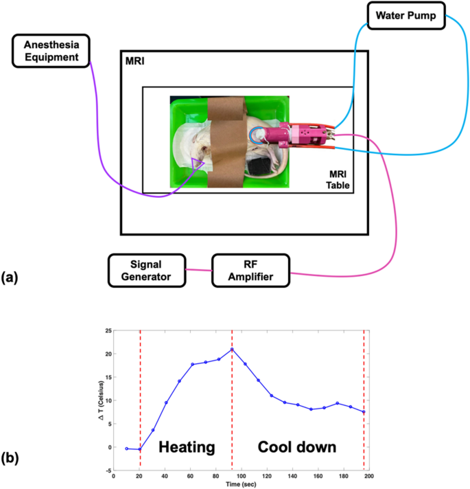
(a) Setup of HIFU experiment. The reflecting HIFU transducer, derived from the RF amplifier, was placed above the rat thigh or pork tenderloin, and the WICS coil was mounted around the transducer. (b) The temperature response shows the heating procedure of the HIFU experiment. HIFU power was turned on for an ultrasonic dose of 30 w/60 s then turned off for tissue cool-down until end of scanning.
All T2-weighted images were applied with parameters of FOV = 230 × 184 mm2, matrix size = 400 × 256, TR/TE = 3000/80 ms. Sagittal sections were used for positioning and SNR comparison. All temperature mapping were applied with parameters of TR = 16 ms, TE = 12 ms, flip angle = 30 (^circ ), matrix 128 × 128, FOV = 128 × 128 mm2, slice thickness = 3 mm, and slice number = 4 in coronal sections. All MR raw data was reconstructed and analyzed offline in Matlab R2016b (MathWorks, MA, USA).
Ex vivo experiments
Ex vivo experiments were separated into two parts, including a temperature measurement comparison study and a SNR comparison study. The temperature measurement comparison study was performed on pork tenderloins (250–350 g, n = 7) and hind legs of deceased rats (250–350 g, n = 5), using a clinically used body coil as the transmit coil and an 8-channel human head coil as the receiving coil.
-
1)
Pork tenderloins: Pork tenderloins were purchased from the local supermarket and placed in the scan room at room temperature for two hours before the experiment. The experimental setup is shown in Fig. 2(g) and described above. The experimental setup and anatomical localization scan took approximately 20 min. T2-weighted images were used for positioning. After T2 images were acquired, thermal mapping both without and with HIFU ablation was performed using spoiled GRE pulse sequences. After scanning for 30 s, HIFU ablation was applied at 30 W for 60 s, and then HIFU power was turned off to allow the tissue to cool-down. Ablation procedure is shown in Fig. 4(b).
-
2)
Rat: Deceased rats were stored frozen. Before the experiment, deceased rats were soaked in room temperature water to thaw for two hours and placed in the scan room at room temperature for one hour. Fur on the rat thighs were shaved to improve deposition of ultrasound beam into the tissue. Rats were placed in the right recumbent position without WICS coil to obtain reference images. Rats were then moved to the left recumbent position, and the WICS coil was placed on the right hind thigh inside the receive coil. The experimental setup, process and MRI protocols are the same as those mentioned in the “Pork tenderloins” subsection.
The SNR comparison study was performed on the pork tenderloins (250–350 g, n = 7) and hind legs of deceased rats (250–350 g, n = 5), using the body coil as the transmitting coil and receiving coil. The experiment setup and process are the same as those mentioned in the “Temperature measurement comparison study” section. The primary difference is that in the SNR comparison study, only the body coil is used as the transmitting coil and receiving coil to simplify the SNR calculation. This is because the SNR calculation of the phased array coil is more complicated than single channel coil and it is not necessary for us to know the SNR enhancement of the WICS coil. In addition, we only obtained T2-weighted images and but not thermal mapping because it was not necessary for SNR comparison.
Data analysis
To obtain and evaluate temperature precision with and without using the WICS coil, averaged values and standard deviations were calculated for the square ROIs (25 pixels) on non-heating temperature maps. (Delta mathbf{T}) in the non-heating temperature maps should theoretically be zero. Thus, any detected temperature variation can be interpreted as noise and distinguished easily in the non-heating temperature map.
To evaluate the SNR enhancement from using the WICS coil, we compared the SNR obtained from T2-weighted images with and without WICS coil, using the body coil as the transmitting coil and receiving coil. The ROIs are shown in Fig. 5, and each ROI contains 25 pixels. For pork experiment, three ROIs were drawn on the T2-weighted images at different depths to compare the effect of varying distances from the WICS coil on the SNR (Note that pork tenderloin is homogeneous tissue). For rat experiment, only one ROI was drawn on T2-weighted images at the position close to the WICS coil. The SNR was calculated as the ratio of the mean ROI signal in the rat thigh or pork tenderloin to the standard deviation of the phantom signal (Eq. 4). A two-sample t-test was conducted to compare the SNRs of the ROIs of the T2-weighted images obtained with and without WICS coil. Comparison of SNR versus distance profile with and without WICS coil of ex vivo pork experiment was also shown.
$$ SNR = frac{{S_{s} }}{{SD_{n} }} $$
(4)
Figure 5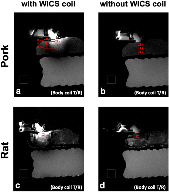
Representative T2 weighted images of rats (bottom row) and pork tenderloins (top row) obtained with (a, c) and without (b, d) WICS coil from ex vivo experiments. Each ROI contains 25 pixels for SNR measurement, as shown in red rectangles.
where, ({S}_{s}) (signal parameter) is the mean intensity value within the signal ROI in pork tenderloin or rat, and ({SD}_{n})(noise parameter) is the standard deviation of intensity values within the background noise ROI.
In vivo experiments
The in vivo animal experimental protocols were approved by the Institutional Animal Care and Use Committee of National Taiwan University. All the procedures were carried out in accordance with relevant approved guidelines and regulations. All animal protocols were performed in compliance with the ARRIVE guidelines. An adult Sprague–Dawley rat (250–350 g) were used in the in vivo experiment. Besides the anesthetization and euthanasia procedure, the experimental setup, process and MRI protocols are identical to the “ex vivo experiments” subsection but excluding the control experiment without WICS coil. The rat was placed in an anesthesia box and administered induction anesthesia by inhalation of 4% isoflurane. After setting up the rat on the MRI table, maintenance anesthesia was administered through continuous inhalation of 2.5% isoflurane via the mask cone. MR images were acquired with the WICS coil using the body coil as the transmit coil and receive coil. After the MRgHIFU ablation experiment, the rat was anesthetized by inhalation of 5% isoflurane and sacrificed by guillotine.


